Types of Ceramic Capacitors and Their Uses
2026-04-27
39
Catalog
What are Ceramic Capacitors?
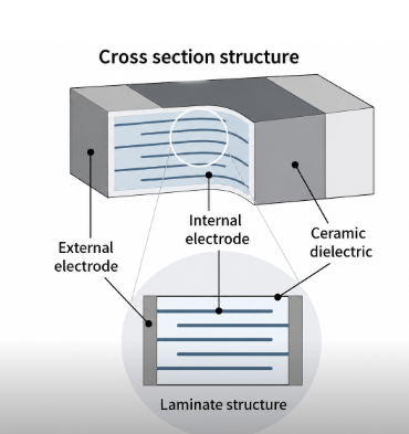
Ceramic capacitors are widely used for filtering, coupling, decoupling, and energy storage. Most modern designs use MLCCs (Multilayer Ceramic Capacitors), which stack alternating ceramic and metal layers to achieve high capacitance in very small packages.
The main factor that defines performance is the dielectric material, as it directly influences how the capacitor behaves under different conditions. It determines how stable the capacitance remains across temperature changes, how sensitive the component is to applied DC voltage (known as the DC bias effect), how the capacitance gradually changes over time due to aging, and how effectively the capacitor responds across different frequency ranges.
In practice, two capacitors with the same nominal value (e.g., 10 µF) can behave very differently depending on their dielectric.
What the 3-Character Capacitor Code Means?
Many ceramic capacitors use a three-character code:
Letter + Number + Letter
• First letter → minimum temperature
• Number → maximum temperature
• Last letter → capacitance variation
Examples:
• X7R: -55°C to 125°C, ±15%
• X5R: -55°C to 85°C, ±15%
• Y5V: -30°C to 85°C, up to -82%
This mainly applies to Class 2 and Class 3 capacitors.
Types of Ceramic Capacitors
Ceramic capacitors are grouped into three classes based on stability and performance, with each class defined by its dielectric type.
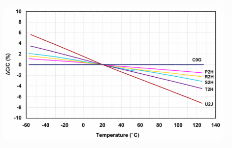
Figure 2. Capacitance vs Temperature: Stable C0G vs Varying Dielectrics
Class 1: High Stability (C0G / NP0)
C0G (NP0) capacitors provide very stable capacitance with no DC bias effect and no aging.
They offer minimal capacitance change and are ideal for RF circuits, oscillators, and precision analog applications.
If your circuit depends on accuracy or timing, C0G is often the only safe choice. Even though capacitance values are lower and cost is higher, the performance is predictable and reliable.
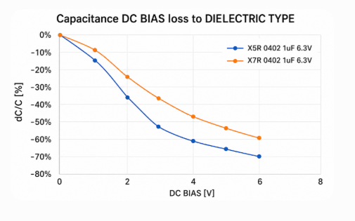
Figure 3. DC Bias Effect Showing Capacitance Loss in X7R and X5R
Class 2: General Purpose (X7R, X5R)
These are the most commonly used capacitors in modern electronics because they offer a good balance between size, cost, and performance.
• X7R (Most Versatile Choice)
Main characteristics include operation up to 125°C, moderate capacitance stability of ±15%, and a noticeable reduction in capacitance under DC bias conditions, along with gradual aging over time.
Typical uses include decoupling and bypassing, supporting stable operation in digital circuits, and general-purpose filtering across a wide range of electronic applications.
In practice, a 100 nF X7R capacitor may only deliver around 60–80 nF when operating under typical voltage and temperature conditions due to capacitance loss caused by DC bias and environmental factors.
• X5R (High Capacitance in Small Size)
Main characteristics include a lower operating temperature range of up to 85°C, higher capacitance density in a compact size, and increased sensitivity to DC bias, which can noticeably reduce effective capacitance under applied voltage.
Typical uses include supporting power rails, providing bulk decoupling, and enabling high capacitance in compact electronic designs where space is limited.
In space-constrained designs, X5R capacitors are commonly used because they offer high capacitance in small packages, but you need to account for capacitance loss under applied voltage to ensure reliable performance.
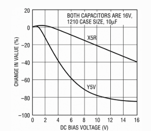
Figure 4. Severe Capacitance Loss in Y5V under DC Bias Compared to X5R
Class 3: Low Stability
This type is best suited for cost-driven designs where performance is not a primary concern.
Main characteristics include very high capacitance per unit volume, extremely poor stability, severe capacitance loss under voltage and temperature variations, and noticeable aging over time.
Typical uses include low-cost applications where performance stability is not important.
An important point to note is that a 10 µF Y5V capacitor can behave like 2 µF or even less under typical operating conditions.
Comparing C0G, X7R, X5R, and Y5V
Figure 5. Capacitance vs Temperature for C0G, X7R, X5R, Y5V, and Z5U
|
Characteristic |
C0G
(Class 1) |
X7R
(Class 2) |
X5R
(Class 2) |
Y5V
(Class 3) |
|
Stability |
Excellent |
Moderate (±15%) |
Moderate (±15%) |
Very poor |
|
DC Bias Effect |
None |
Moderate loss |
Moderate loss |
Severe loss |
|
Aging |
None |
Gradual |
Faster |
Noticeable |
|
Frequency Performance |
Excellent |
Moderate |
Moderate |
Poor |
|
Best Use |
Precision circuits |
General decoupling |
Compact power / bulk |
Low-cost only |
Layered Decoupling for Power Integrity
Effective decoupling uses multiple capacitor types together, as each dielectric performs best over a different frequency range. A single capacitor cannot cover all frequencies, so a layered approach is required.
Use the following combination:
|
Frequency
Range |
Capacitor
Type |
Typical
Value |
Placement |
|
High frequency |
C0G |
10 nF to 100 nF |
Closest to IC power pins |
|
Mid frequency |
X7R |
100 nF to 1 µF |
Near the IC |
|
Low frequency |
X5R |
10 µF or larger |
Bulk energy storage (power rail) |
This combination improves noise filtering and overall power stability.
Common Application Examples
• Microcontroller decoupling - X7R 100 nF
• RF oscillator or timing circuit - C0G
• Power rail smoothing - X5R 10 µF+
• Low-cost electronic device - Y5V (only if variation is acceptable)
How to Choose the Right Capacitor?
Step 1: Start with your goal
• Precision / timing → C0G
• General-purpose → X7R
• High capacitance in small space → X5R
• Cost-only designs → Y5V
Step 2: Don’t trust nominal capacitance
Capacitance drops under DC bias and temperature.
Always add margin to ensure enough capacitance in operation.
Step 3: Consider long-term stability
• C0G → stable for years
• X7R/X5R → gradual drift
• Y5V → large variation over time
Step 4: Balance size and cost
Smaller packages can lose more effective capacitance under DC bias.
Don’t choose size based on footprint alone.
Step 5: Validate under actual conditions
Test in the actual circuit by evaluating voltage ripple, noise performance, and overall stability. Final performance depends on operating conditions, not just datasheet values.
Reliability and Manufacturing Risks
Even correct designs can fail due to improper handling and assembly. Mechanical stress is a common issue, especially for large MLCCs, which can crack when the PCB bends. Using smaller components or soft-termination capacitors can help reduce this risk.
Batch variation is another concern, especially with X7R and X5R capacitors, as their performance can vary between production lots. It is important to test main components before use to ensure consistency.
Thermal shock can also lead to failure. Rapid temperature changes during soldering or cooling may cause internal cracks. Following proper reflow profiles and controlled heating processes helps prevent this type of damage.
Conclusion
Choosing the right ceramic capacitor improves stability, reduces noise, and ensures reliable performance. Use C0G for precision, X7R for general use, X5R for higher capacitance, and Y5V only when cost is the priority. Always consider DC bias, temperature, aging, and actual operating conditions before making a final choice.
Funktionstest.Die höchsten kostengünstigen Produkte und der beste Service sind unser ewiges Engagement.
Heißer Artikel
- LM358 Doppeler Betriebsverstärker umfassender Anleitung: Pinouts, Schaltpläne, Äquivalente, nützliche Beispiele
- Sind CR2032 und CR2016 austauschbar?
- Verständnis der Unterschiede ESP32- und ESP32-S3-technischer und Leistungsanalyse
- Auswahl der richtigen Batterie: Eine Anleitung zu AG4, LR626, LR66, 177/376/377, SR626 und SR626SW -Äquivalenten
- NPN vs. PNP: Was ist der Unterschied?
- Grundlagen des BC547-Transistors: Pinbelegung, Anwendungsschaltungen, alternative/komplementäre Modelle
- ESP32 VS STM32: Welcher Mikrocontroller ist besser für Sie?
- Was ist ein MOSFET und wie funktioniert es?
- Elektro -Relais Basic: Arbeitsbetrieb, Typen und Verwendungen
- PNP -Transistoren: Struktur, Arbeitsprinzip und Anwendung
 How to Wire a 4-Pin & 5-Pin Relay
2026-04-27
 Selbsthaltendes oder nicht selbsthaltendes Relais: Was ist besser?
2026-04-27
Häufig gestellte Fragen [FAQ]
1. What are common design mistakes when selecting ceramic capacitors?
A common mistake is relying only on nominal capacitance without considering DC bias, temperature, and aging. This often leads to insufficient capacitance in actual operation.
2. How does capacitor aging impact long-term circuit reliability?
Class 2 and Class 3 capacitors gradually lose capacitance over time. In long-life products, this can lead to performance drift or instability if not accounted for in the design margin.
3. When should C0G be chosen over X7R despite lower capacitance?
C0G should be used when stability, accuracy, and low noise are important, such as in RF circuits, oscillators, and precision analog designs.
4. How does capacitor package size affect performance under load?
Smaller packages tend to show greater capacitance loss under DC bias. Larger packages generally maintain more stable effective capacitance in power applications.
5. What is the impact of temperature variation on ceramic capacitor performance?
Temperature changes can shift capacitance noticeably, especially in X5R and Y5V. In extreme conditions, this can affect timing, filtering, and overall circuit behavior.
6. How do you choose the right capacitor for power supply decoupling in modern electronics?
A layered approach is recommended, combining C0G for high frequency, X7R for mid frequency, and X5R for bulk energy storage to ensure stable power delivery.
7. How can you verify capacitor performance before finalizing a design?
Testing under actual operating conditions, including voltage, temperature, and load, is important. Simulation and lab validation help confirm real performance beyond datasheet values.Heiße Teilenummer
 UMK105B7104MV-FR
 GCM1555C1H1R2CA16J
 GRM188R72A391KA01D
- GJM1555C1H7R9CB01D
 04023U2R4BAT2A
 GRM15XR61A153MA86D
 CGJ4J2X7R1E333K125AA
 12101C333JAT2A
 GA342A1XGD560JW31L
- UMK105CG5R6BW-F
- TAJA107K004RNJ
- TAJE476M025RNJ
- DF22A-1012SCF
- MAX3238EAI
- NJM2132M
- ISL6722AAVZ
- 74HC595T16-13
- CY7C67300-100AXIT
- VI-2WB-MV
- RT0402DRD0730RL
- MCR03EZPJ103
- RC0805FR-07240KL
- T491C226M016ZTZ012
- T495X226K035ZTE130
- TPS62008DGSR
- ADUC7021BCPZ32
- T491A155M025ZT
- TMS470R1A256PZ-T
- AD8349AREZ-RL7
- PCI2060ZHK
- CY2292SC-32T
- EDJ1104BDSE-GL-F
- IR35411MTRPBF
- P202EPSE2KFB
- PPC5554MZP
- R5F364V6NFB
- SPM1423HM4H-B-6
- ALC203-LF
- A45L9332F-7
- APQ8064-3AB
- NP3454PRCB-350
- S11059-01WT
- M29F040B-70K6T
- TPS61160ADRV
- TY8A0A111574KA
- CN5230-700BG729-CP-Y-G
- DC20/20EWA
- ADM7150ACPZ-5.0-R2
- UPD70F3452GC