How to Wire a 4-Pin & 5-Pin Relay
2026-04-27
81
Catalog
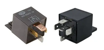
Figure 1. 4-Pin vs 5-Pin Relay Example
What Is a Relay and Why Is It Used in Circuits?
A relay is an electrically controlled switch that lets you use a small signal to control a bigger device. When you send power to the relay, it activates a coil inside, which moves a contact and turns another circuit on or off. This means you can use something low-power, like a microcontroller or a simple switch, to control devices that need higher power, such as lights, fans, or motors.
You use a relay when you need to control high voltage or high current safely. Relay keeps your control circuit separate from the power circuit, so your components stay protected. Relay also makes it easier for you to automate systems, since the relay can switch devices on and off based on electrical signals.
How Does a Relay Work?
When you apply voltage to a relay, current flows through a coil inside it. This creates a magnetic force that pulls a metal contact. When the contact moves, it changes the path of the circuit, allowing current to either flow or stop. This movement is what controls the connected device.
A relay has specific pins that handle different parts of this process. Pins 85 and 86 are used to power the coil. Pin 30 is the main connection, and it switches between pin 87 (normally open) or pin 87a (normally closed, if available). When the relay is not powered, the contact stays in its default position. When power is applied, the contact moves and changes the connection.
Once the power is removed, the magnetic force disappears, and a spring returns the contact to its original position. This allows the relay to switch back and be ready for the next signal. To understand how each connection works clearly, let’s look at the relay pin layout in the next section.
Relay Pinout Configuration
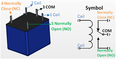
Figure 2. Relay Pinout and Symbol Diagram
Pins 85 and 86 (Coil) - These pins control the relay. You connect one to power and the other to ground. When voltage is applied, the relay is activated.
Pin 30 (Common) - This is the main input connection. It carries the power that will be switched to another pin.
Pin 87 (Normally Open - NO) - This pin is not connected to pin 30 when the relay is off. When the relay turns on, pin 30 connects to pin 87, allowing current to flow.
Pin 87a (Normally Closed - NC) - This pin is only found in 5-pin relays. It is connected to pin 30 when the relay is off. When the relay turns on, this connection is disconnected.
4-Pin vs 5-Pin Relay: What Is the Difference?
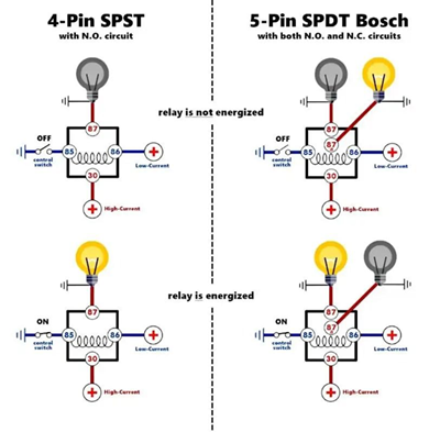
Figure 3. 4-Pin vs 5-Pin Relay Operation Diagram
The difference between a 4-pin and a 5-pin relay is the number of switching options they provide. Both types use pins 85 and 86 for the coil and pin 30 as the common connection. The difference is in how the output is handled.
A 4-pin relay has only one output, which is pin 87. This is a normally open (NO) connection, meaning the circuit is off by default. When the relay is activated, pin 30 connects to pin 87, and the device turns on. This type is simple and is commonly used when you only need to turn something on when power is applied.
A 5-pin relay adds an extra pin, 87a. This is a normally closed (NC) connection. When the relay is off, pin 30 is connected to 87a. When the relay is activated, the connection switches from 87a to 87. This gives you more control because you can choose between a default ON or default OFF behavior.
4-Pin vs 5-Pin Relay Comparison Table
|
Feature |
4-Pin
Relay |
5-Pin
Relay |
|
Number of Pins |
4 |
5 |
|
Coil Pins |
85, 86 |
85, 86 |
|
Common Pin |
30 |
30 |
|
Output Pins |
87 only |
87 and 87a |
|
Normally Open (NO) |
Yes (Pin 87) |
Yes (Pin 87) |
|
Normally Closed (NC) |
No |
Yes (Pin 87a) |
|
Default State (Relay
OFF) |
Circuit is open (OFF) |
Connected to 87a (ON
by default) |
|
When Relay is ON |
30 connects to 87 |
30 switches from 87a
to 87 |
|
Switching Options |
Single path |
Two paths (NO and NC) |
|
Complexity |
Simple |
More flexible |
|
Common Use |
Basic ON/OFF control |
Circuits needing
default ON or OFF control |
4-Pin vs 5-Pin Relay Parameters and Differences
Both 4-pin and 5-pin relays share similar basic functions but they differ in switching capability and flexibility.
|
Parameter |
4-Pin
Relay |
5-Pin
Relay |
|
Number of Pins |
4 |
5 |
|
Coil Pins |
85, 86 |
85, 86 |
|
Common Pin |
30 |
30 |
|
Output Pins |
87 only |
87 and 87a |
|
Contact Type |
Normally Open (NO) |
Normally Open (NO) +
Normally Closed (NC) |
|
Default State |
OFF (open circuit) |
ON or OFF depending
on connection |
|
Switching Paths |
One path |
Two paths |
|
Control Flexibility |
Limited |
More flexible |
|
Typical Coil Voltage |
12V (common) |
12V (common) |
|
Current Rating |
10A–30A (typical) |
10A–30A (typical) |
|
Typical Use |
Simple ON/OFF control |
Advanced control with
default state |
4-Pin Relay Wiring Diagram
To wire a 4-pin relay, you just need to connect the control side and the load side correctly. Once you follow the right pin connections, the relay will switch your device on when triggered.
First, connect pin 85 and pin 86 to the control circuit. One pin goes to power, and the other goes to ground. You can place a switch on this side so you can control when the relay activates. Next, connect pin 30 to your main power source. This is the input power that will be sent to your device when the relay turns on. It is a good idea to place a fuse between the power source and pin 30 for protection.
Then, connect pin 87 to your load, such as a light, fan, or motor. This is the output that will receive power when the relay is activated. Finally, connect the other side of your load to ground. This completes the circuit.
When you turn on the control switch, the relay activates. Pin 30 connects to pin 87, and current flows to your device, turning it on. When you turn it off, the connection is broken, and the device turns off.
5-Pin Relay Wiring Diagram
To wire a 5-pin relay, you follow a setup similar to a 4-pin relay, but with one extra connection that gives you more control.
Start by connecting pin 85 and pin 86 to the control side. One goes to power, and the other goes to ground. You can add a switch here to control when the relay turns on. Next, connect pin 30 to your main power source. This is the input power that will be switched to the output.
Then, decide how you want your device to behave:
• If you want the device OFF by default, connect your load to pin 87 (normally open). The device will only turn on when the relay is activated.
• If you want the device ON by default, connect your load to pin 87a (normally closed). The device will turn off when the relay is activated.
Lastly, connect the other side of your load to ground to complete the circuit.
4-Pin vs 5-Pin Relay in Cooling Fan Control
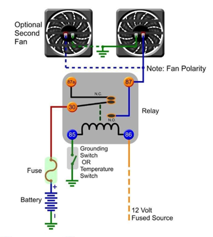
Figure 4. Simple Cooling Fan Relay Wiring Example
When controlling a cooling fan, the choice between a 4-pin and a 5-pin relay affects how the fan behaves by default and during operation.
With a 4-pin relay, the fan stays OFF by default and only turns ON when the relay is activated, such as when a temperature switch sends a signal.
With a 5-pin relay, you can wire the fan to be ON by default using the normally closed (87a) connection, and turn OFF when the relay is activated.
Another advantage of the 5-pin relay is flexibility. It can switch between two states, allowing more control over the fan’s behavior without adding extra components. However, this also makes the wiring slightly more complex compared to a 4-pin relay.
Common Relay Wiring Mistakes and How to Avoid Them
Connecting the wrong pins - If you mix up the pins, the relay won’t work. Double-check the pin numbers before you connect anything.
Skipping the fuse - If you don’t add a fuse, a short circuit can damage your wiring. Always place a fuse on the power line going to pin 30.
Using the wrong voltage - If your relay is rated for 12V and you use a different voltage, it may fail. Make sure your power matches the relay rating.
Bad ground connection - If the ground is weak or missing, the relay won’t activate. Make sure your ground connection is clean and secure.
Loose wiring - Loose wires can cause the relay to turn on and off randomly. Secure all connections properly.
Overloading the relay - If you connect a device that draws too much current, the relay can overheat. Check the relay’s current rating first.
Using 87a without knowing it - Pin 87a is active when the relay is off. If you use it by mistake, your device may stay on when you don’t expect it.
Using a Relay for Car Headlights
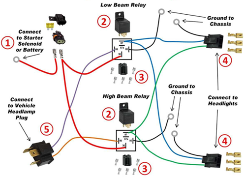
Figure 5. Dual Headlight Relay Wiring Diagram
Using a relay for car headlights helps you control high-power lights safely without putting too much load on the headlight switch.
In many vehicles, the headlight switch is not designed to carry high current for long periods. If you connect headlights directly, the switch and wiring can heat up and wear out over time. By adding a relay, the switch only handles a small control current, while the relay carries the higher current needed by the headlights.
In a typical setup, the battery is connected to pin 30 through a fuse. The headlights are connected to pin 87, which supplies power when the relay is activated. Pins 85 and 86 are connected to the headlight switch and ground, allowing the relay to turn ON when you use the switch.
Applications of Relays in Electrical Circuits
Headlights - A relay allows a small switch inside the car to control the headlights without carrying high current through the dashboard wiring.
Horns - The relay helps deliver enough current to the horn while keeping the steering wheel switch safe from high load.
Cooling Fans - Used to automatically turn the radiator fan on or off based on temperature without overloading the control circuit.
Fuel Pumps - The relay controls the fuel pump operation, allowing it to turn on only when needed for safety and efficiency.
Interior Lighting - Helps manage cabin lights, especially for automatic on/off functions like door-triggered lighting.
Home Lighting Systems - Used to switch lights on or off using low-power controls such as timers or sensors.
Electric Motors - Allows small control signals to start or stop motors in appliances or machines.
Alarm Systems - Used to activate sirens or alerts when a trigger signal is detected.
Microcontroller Projects - Lets devices like Arduino or other controllers safely operate higher-power loads like lamps or fans.
Using a Relay in a Microcontroller Project
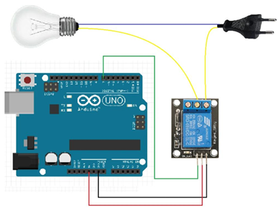
Figure 6. Arduino Relay Control Circuit Example
When you are working with a microcontroller, you cannot directly connect high-power devices like lamps, fans, or motors to its output pins. The microcontroller only provides a small amount of voltage and current, which is not enough to drive these devices safely. This is why a relay is used as a bridge between the low-power control side and the high-power load.
In a common setup, the microcontroller sends a small signal to a relay module. Inside the module, a transistor helps switch the relay on, and a diode protects the circuit from voltage spikes when the relay turns off. Once the relay is activated, it connects the main power source to the device, allowing it to turn on. When the signal stops, the relay opens the circuit and the device turns off.
Safety Tips When Wiring Relays
When wiring a relay, you should always start by adding a fuse to the power line going to pin 30. This protects your circuit in case of a short. Make sure the relay you are using matches your system voltage, such as using a 12V relay for a 12V supply. Using the wrong voltage can damage the relay.
You also need to check the current rating of the relay before connecting any load. If the device draws too much current, the relay can overheat or fail. Use the correct wire size as well, since thin wires can heat up and become unsafe when carrying higher current.
Keep all your connections tight and secure. Loose wires can cause unstable operation or even sparks. Make sure the ground connection is solid, because a weak ground can prevent the relay from working properly.
Before you start wiring, always disconnect the power source. This helps you avoid electric shock or accidental short circuits. After wiring, make sure no wires are exposed and all connections are properly insulated to keep the circuit safe.
4-Pin vs 5-Pin Relay: Which One Should You Use?
The choice between a 4-pin and a 5-pin relay depends on how you want your device to behave and how much control you need in your circuit.
A 4-pin relay is the better choice if you only need simple ON/OFF control. It uses a normally open (NO) connection, which means your device stays OFF by default and only turns ON when the relay is activated. This makes it ideal for applications like headlights, fans, horns, or any device that should only run when triggered. It is also easier to wire and less confusing, especially if you are just starting.
A 5-pin relay gives you more flexibility. In addition to the normally open (NO) pin, it includes a normally closed (NC) pin (87a). This allows you to choose how your device behaves when the relay is off. You can set it so the device is ON by default and turns OFF when activated, or the opposite. This is useful in systems where you need automatic switching between two states, such as safety circuits, signal switching, or backup control.
Another main point is control options. A 4-pin relay has only one switching path, while a 5-pin relay can switch between two paths. This means a 5-pin relay can handle more complex setups without needing extra components.
Conclusion
Relays are simple parts that help you control high-power devices using a small signal. Once you understand how they work and how the pins are connected, wiring them becomes easier. By following the correct steps and safety tips, you can avoid problems and make your circuit work properly. With this knowledge, you can use relays with more confidence in your own projects.
Funktionstest.Die höchsten kostengünstigen Produkte und der beste Service sind unser ewiges Engagement.
Heißer Artikel
- LM358 Doppeler Betriebsverstärker umfassender Anleitung: Pinouts, Schaltpläne, Äquivalente, nützliche Beispiele
- Sind CR2032 und CR2016 austauschbar?
- Verständnis der Unterschiede ESP32- und ESP32-S3-technischer und Leistungsanalyse
- Auswahl der richtigen Batterie: Eine Anleitung zu AG4, LR626, LR66, 177/376/377, SR626 und SR626SW -Äquivalenten
- NPN vs. PNP: Was ist der Unterschied?
- Grundlagen des BC547-Transistors: Pinbelegung, Anwendungsschaltungen, alternative/komplementäre Modelle
- ESP32 VS STM32: Welcher Mikrocontroller ist besser für Sie?
- Was ist ein MOSFET und wie funktioniert es?
- Elektro -Relais Basic: Arbeitsbetrieb, Typen und Verwendungen
- PNP -Transistoren: Struktur, Arbeitsprinzip und Anwendung
 Types of Ceramic Capacitors and Their Uses
Häufig gestellte Fragen [FAQ]
1. Can I replace a 4-pin relay with a 5-pin relay?
Yes, you can use a 5-pin relay as a replacement by using pin 30 and 87 only. Just leave pin 87a unused if you do not need the normally closed function.
2. How does relay isolation protect sensitive components?
The coil and contact sides are electrically separate, so high voltage on the load side does not reach the control circuit, protecting devices like microcontrollers.
3. What happens inside a relay when voltage is applied to the coil?
The coil creates a magnetic field that pulls a contact arm, changing the connection from its default state to an active switching state.
4. Why are pins 85 and 86 interchangeable in some relay circuits?
In basic relays, the coil is not polarity-sensitive, so either pin can be connected to power or ground unless a diode is built in.
5. How do you choose between normally open (NO) and normally closed (NC) contacts?
Use NO when you want the device OFF by default, and NC when you want it ON by default or need a fail-safe condition.
6. Why is a 5-pin relay more flexible than a 4-pin relay?
A 5-pin relay provides both NO and NC contacts, allowing you to switch between two circuit states instead of just turning one ON.
7. Why is a relay used instead of directly connecting a switch to a load?
A relay allows a low-power control signal to safely switch a high-power load. Direct connection can damage switches or control circuits due to high current or voltage.
Heiße Teilenummer
 EMK063BJ221MP-F
 0603YC392MAT2A
 GRM1885C2A5R1DA01D
- 06031C472JAZ2A
 04023A271KAT2A
 GRM219R61E225MA12D
 CC1206FRNPO9BN272
 GQM1555C2D9R7WB01D
 1812WC470KAT1A
 UMK107CG331JZ-T
- FZT953TA
- EPM7160EQC160-20
- EPM7256AETI144-7
- PIC24FJ256GA106-I/MR
- MAX355CWE
- MIC2076-2YM
- VI-2WH-CV
- HEDL-5540#A13
- 7MBR10SA120-70
- CM30AD12A-12H
- QM100TX-HB
- S912ZVML32F3VKH
- XC18V02PC44I
- LT1129IS8-5#TRPBF
- AD976AARZ-RL
- T491C476M020AT
- LP2986IMM-3.3/NOPB
- T491C106M016ATZQ017280
- DB3350CT/3P0P12
- ICS476G10LF
- MAX2430IEE
- MC145480DW
- OR2T10A5J160
- SPL08A2-16C
- STI5517AUBL
- TLE8104ES1
- UCC3961DTRG4
- UPD78062GF-059
- AT24C256CI1.8
- M44C260I
- PC82801HUX
- 6MBI20GS-I060
- M38869M8A
- TPS79901DDC
- ST1912-T100
- TG83-1505NURLTR
- FS32K116LFT0MLFR
- 1812HC821MAT3A
- SNBB028NIC